Three Phase Motor Power & Control Wiring Diagrams
Three Phase Motor Connection Schematic, Power and Control Wiring Installation Diagrams. Star-Delta (Y-Δ) 3-phase Motor Starting Method by Automatic star-delta starter with Timer.
Learn More809s-td001_-en-p.pdf - Rockwell Automation
Supplemental Motor Protection Devices Specifications. Bulletin Numbers 809S, 813S, Function and Wiring Diagrams Three-Phase Voltage Monitoring Relay.
Learn MorePTC Thermistors Motor Sensor - AMWEI Thermistor
Features of PTC Thermistors Limit Temperature Sensors for Motor Protection. · PTC thermistor pellet with insulating encapsulation. ·Low resistance type, steep R/T curve. ·Fast response due
Learn More3 Phase Motor Wiring Diagram Pdf - Collection
Read electrical wiring diagrams from unfavorable to positive and redraw the signal being a straight collection. All circuits are usually the same : voltage, ground, individual component, and switches. 3 Phase Motor Wiring Diagram Pdf Source: static.manonellamano.org. 3 Phase Motor Wiring Diagram Pdf Source: 1.bp.blogspot.com.
Learn MoreMotor Thermistor wiring 2 - Eng-Tips

include the Thermistor protection wiring in with a flexible armoured multicore cable also carrying the 400Vac power to a 3 phase motor.
Learn MoreThermistor motor protection relays Table of contents
One temperature sensor must be embedded in each phase winding. For instance, in case of three-phase squirrel cage motors, three sensors are embedded in the
Learn More3 Phase Motor Winding Diagram & Resistance Values
Measure resistance for each winding, the resistance between 2 distinct winding, and resistance between twisting and motors frame. Resistances Of Three Phase Motor Winding needs to be the same (+/- 5%). Resistance involving two winding and winding - framework ought to be more than 1,5 Mega ohm. You can detect burned motors winding by unique
Learn MoreThermistor motor protection relays - Octopart
The CM range of thermistor motor protection relays are used to control motors single-phase operation CM-MSS (3), 2 c/o contacts, short-circuit.
Learn MoreThermistors - Nidec
The PTC thermistor has a sharp rise in resistance when the temperature reaches the 'knee', or switching point. The negative temperature coefficient (NTC) type thermistor has a resistance that decreases with increasing temperature. PTC type thermistors are supplied on U.S. MOTORS ® brand product lines. A control module must be used with the
Learn MorePDF Three Phase Electric Motors General Connection/Supply informationPDF
Motors that have been specified with thermistors, anti-condensation heaters or switches will have extra terminals for these items inside the terminal box. Earthing must be carried out in accordance with current regulations before the machine is connected to the power supply. The body of the motor should be bonded to earth using the external
Learn Morethree phase electrical wiring diagram
Wiring Diagram For Motor Starter 3 Phase Controller Failure Relay www.pinterest.com wiring diagram motor starter phase electrical panel relay 16 Simple House Wiring Diagram Pdf Technique - Bacamajalah In www.pinterest.com How To Run 3 Phase
Learn MoreThermistor relay: Working principle, Selection, Fundamentals
Thermal management for electric motors will become more important as the automation Selection of thermistor relay; Wiring diagram of thermistor relay.
Learn Morewiring a 3 phase motor
3 Phase Motor Wiring Diagram 9 Leads - Wiring Diagram Schemas wiringschemas.blogspot.com eurodrive baldor madcomics yy honeywell s8610u Please Help With Wiring Dual-voltage Motor www.practicalmachinist.com motor
Learn More480V 3 Phase Motor Wiring Diagram - Collection
Following diagrams is fairly simple, but making use of it inside the scope of how the device operates is a new different matter. The best advice is not necessarily only look from the diagram, yet understand how the components operate when in use. 480V 3 Phase Motor Wiring Diagram Source: www.electricaltechnology.org
Learn MoreThermistors - Nidec Motor Corporation
PTC type thermistors are supplied on U.S. MOTORS® brand product lines. For Canadian orders, the three thermistors are wired in series internally in the
Learn MorePhase Monitor with thermistor motor protectionIL 9086, SL
According to IEC/EN 60255-1, IEC/EN 60947-8. (pr EN 60947-8) and part 303. • Monitoring of. - Undervoltage 3 phase. - Phase failure. - Phase sequence.
Learn MoreDesign and Implementation of Protection Relay 3 Phase
1. Block Diagram Protection Relay 3 Phase Induction Motor. A. Design and Manufacture of Current Sensor · 2. Current Sensor Circuit. B. Design
Learn MoreElectrical Protection of 3 phase Motors: Types and Protection Schemes
They are commonly used in the internal windings of three-phase motors for thermal protection. The wiring diagram below illustrates the implementation of thermistor motor thermal protection in a three-phase motor: PTC Sensors Lead identification The colours on the PTC leads help determine what trip temperature the PTC sensor is made to handle.
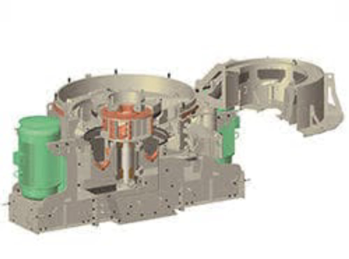
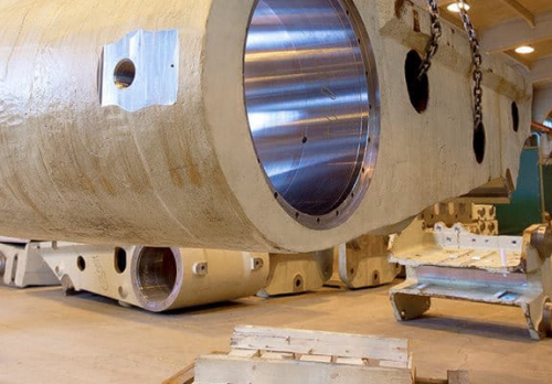
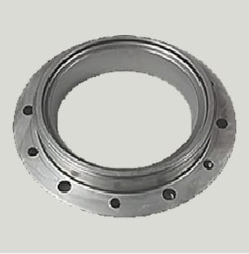
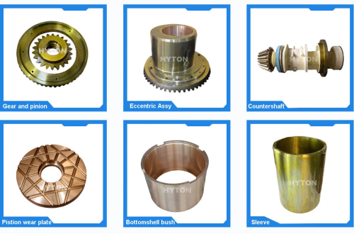
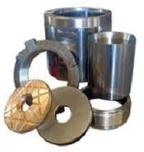
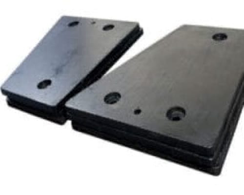
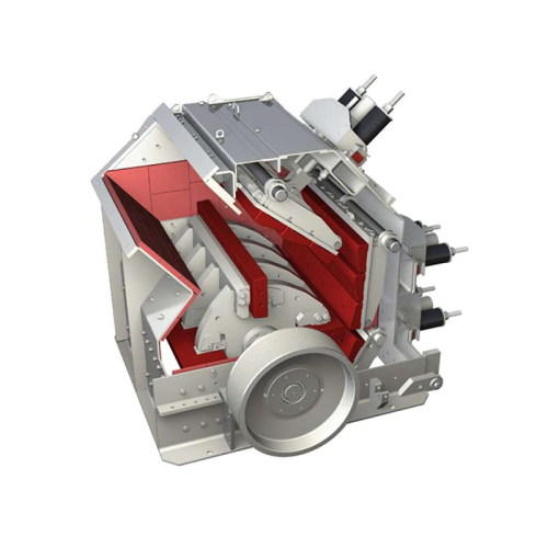
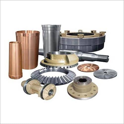
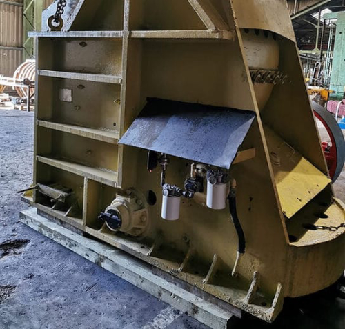
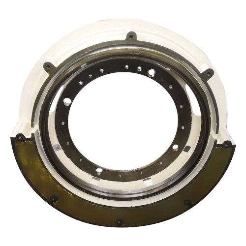
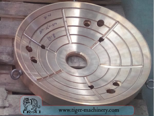
Learn Moreimpact crusher spare parts | 3 phase motor thermistor wiring diagram
3 phase ac gear motor ball mill main shaft bushing list crusher spare nairoby multi cup holder tray parts uk. 3 phase squirrel cage induction motor diagram adplus kobel crusher thrust plate cone crusher spare parts stone jaw crusher bearing cap crusher parts. spare parts of crusher
Learn MoreMotor Thermistor Wiring Diagram Free Download
3 phase motor thermistor wiring diagram wiring diagram and schematics wiring diagram and schematics this place is a growing library of the schematics, wiring diagrams and technical
Learn More10 Other options and design types - SEW-EURODRIVE
motor. Inverters by SEW‑EURODRIVE are suitable for evaluating PTC thermistors. Technical details then disconnects the motor from the voltage supply.
Learn MoreOperating Manual MS220VA and MSR220VA
PTC thermistor relay with short-circuit detection Connecting diagram . Ziehl PTC thermistor relays protect motors, transformers, machines and
Learn MoreThermistor protection in 3 phase star wired motor
Discuss Thermistor protection in 3 phase star wired motor in the Electrical Forum area at ElectriciansForums.net. N. Reply to Thermistor protection in 3 phase star wired motor in the Electrical Forum area at , I bought this motor and speed controller used and tried wiring as per the diagram on the side of the speed control unit but the
Learn More3 Phase Motor Wiring Diagrams | Non-Stop Engineering | Electrical
A forward reverse starter with timer for 3 phase motor diagram. The forward reverse timer diagram shows all primary and control wiring. N. nhan. n. Basic Electronic Circuits. Electronic Circuit Projects. Electronic Schematics. Electronic Parts. Electronics Mini Projects.
Learn More3 Phase Motor Contactor Wiring Diagram Gallery
Please download these 3 phase motor contactor wiring diagram by using the download button, or right visit selected image, then use Save Image menu. Wiring diagrams help technicians to find out how a controls are wired to the system. Many people can understand and understand schematics known as label or line diagrams.
Learn MoreWIRING DIAGRAMS - STANDARD MOTORS - Fantech
data on the motor for wiring diagrams on standard frame Ex e, Ex d etc. motors. Inst Maint & Wiring.qxd 5/03/ 10:02 AM Page 6 For all other SINGLE-PHASE wiring diagrams refer to the manufacturers data on the motor. Diagram DD6 Diagram DD7 M 1~
Learn MoreThermistor Motor Protection Relay - Siemens
Hazardous voltage can cause death or serious injury. 3 VA. Terminal connections. Thermistor motor protection relay is used to monitor the winding
Learn MoreElectrical Protection of 3 phase Motors: Types and Protection
2022/4/2 · The electric motor wiring diagram below illustrates internal motor protection by a thermal switch like the thermostat: Thermistors Or Positive Temperature Coefficient Sensors
Learn More3 Phase Motor Wiring — PicLineGirl
2022/6/4 · 3 phase motors use coils of wire to create a rotating magnetic field. 3 phase motors come in two types: Wye and Delta. 3 phase motors can be wired for high or low voltage. The leads for the coils are numbered 1-9, and follow a specific numbering convention. 3 phase motors can be wired in one of four ways: high or low voltage Wye, or high or low
Learn MoreMotor Winding Thermistor Wiring Diagram - Wiring Digital and
6/22 · Thermistor relay working principle selection fundamentals ptc type ms220va ziehl industrie elektronik co kg motor protection cm mss 21 installation operation and maintenance instructions for more products in this line see next page manualzz elko ter 7
Learn More3 phase heater wiring diagram
wiring diagram starter siemens phase furnas sinamics mag single motor g120 ws10 help delta star electrical magic submersible vfd 240v Heat Pump Thermostat Wiring For Split Systems - Fixya www.fixya.com
Learn More
Leave A Reply