Schneider 24vdc relay wiring diagram - jket.attacksimulator.pl
Wiring Diagrams for MasterPact NW Circuit Breakers. NOTE: All diagrams show circuit breaker open, connected and charged. A. Do not remove factory-installed jumpers between Z3, Z4 and Z5 unless ZSI is connected. B. Do not remove factory-installed jumper between T1 and T2 unless neutral CT is connected. Do not install jumper between T3 and T4.
Learn More3 Safety relays

Safety relays. Preventa™ safety relay modules type XPSAC. For Emergency stop and switch monitoring. Wiring diagrams. Principle: page 3/14. Specifications:.
Learn MoreAllen Bradley GuardMaster Safety Relay Wiring Tutorial - SolisPLC

They're often used in complex applications in which distributed safety is required. In this tutorial, we will take a look at the GuardMaster Dual Input safety relay paired with a SensaGuard safety sensor, understand the application it may be used in, the wiring scheme of both devices, and how they interact with each other.
Learn MoreSchneider Electric Preventa Safety Relay Modules - Nuova Elva

Wiring diagrams. Safety automation solutions. Preventa™ safety relay modules type XPSAC. For Emergency stop and switch monitoring.
Learn MoreSafety - MSR126R/T - Namrata Trade Links

Safety Classification Cat. 4 per EN 954-1 (ISO 13849-1), SIL CL3 per EN IEC 62061, PLe per ISO 13849-1 Block Diagram Typical Wiring Diagrams 115/230V Supply, 24V DC Light Curtain, Monitored Manual Reset, Monitored Output Dual Channel E-Stop
Learn MoreMachine Safeguarding Products - PREVENTA™ XPS Safety

2003 Schneider Electric All Rights Reserved. 18. 05/03. XPSAV and XPSAT Safety modules for emergency stop and switch monitoring. Wiring Diagrams.
Learn MorePDF SNA 4043 K SNA 4044 K SNA 4063 K SNA 4064 K SNA 4043K ... - SchleicherUSAPDF

ISO 13 849-1 depends on external switching, execution of the wiring, selection of command g enerator and its setup on the machine. The relevant actuators on the machine or plant can be safely dea c-tivated via the touch-sensitive switching outputs on the safety relay. The safety relay was designed exclusively for use in conjunction with
Learn MoreWiring diagram - IM400 Series - Schneider Electric

Wiring diagram. All the device wiring terminals have identical wiring capabilities. The following are the list of characteristics of the cables that can be
Learn MoreSPIDER S6000 schneider safety relay wiring diagram
SPIDER S6000 schneider safety relay wiring diagram Technical specifications — Mining and Rock Technology. D245S is a diesel powered, self-propelled crawler mounted blasthole drill for mining. This production drill comes with a low-pressure power group for rotary drilling in medium hard rock conditions like those found
Learn MoreModicon M580 - Safety Manual - - 09/ - Home

When devices are used for applications with technical safety requirements, the relevant instructions must be followed. Failure to use Schneider Electric
Learn MoreNext Generation Guardmaster Safety Relay (GSR) Wiring Diagram
Next Generation Guardmaster Safety Relay (GSR) Notes for Example Wiring Diagrams Note 1 In the wiring diagrams that are shown in this publication, the type of Allen-Bradley® Guardmaster® device is shown as an example to illustrate the circuit principle. For
Learn MorePDF Instruction sheet XPSAF - RS ComponentsPDF

IMPROPER CIRCUIT AND MAINTENANCE HAZARD • Wire safety relay using wiring diagram shown in following wiring diagram. Failure to follow these instructions can result in death or serious injury. • Wire to meet applicable standards requirements. • K3 and K4 must have mechanically-linked contacts.
Learn MorePreventa solutions for efficient machine safety

Schneider Electric provides you with the complete set of industrial Machinery safety - Electrical equipment of machines - Part 1: general requirements.
Learn MorePDF Safety - MSR126R/T - Namrata Trade LinksPDF
The Allen-Bradley Guardmaster Minotaur MSR126R/T is a safety monitoring relay that provides the very basics for safety control Safety Classification Cat. 4 per EN 954-1 (ISO 13849-1), SIL CL3 per EN IEC 62061, PLe per ISO 13849-1 Block Diagram Typical Wiring Diagrams. 115/230V Supply, 24V DC Light Curtain, Monitored Manual Reset
Learn MoreXPSAK311144P Safety Relay (Schneider Electric

XPSAK311144P Safety Relay Dual Channel with 3 Safety Contacts and 1 Auxilary Contact (Schneider Electric) Two-hand control safety circuits.
Learn MoreSafety Relays - Where and How They Work - Galco

Emergency off/stop. Operating a Safety Relay. A phoenix contact safety relay wiring diagram. Safety relays are simple to operate and have a clear structure.
Learn MoreSafety relays | SICK

The wide range of safety solutions from SICK – from a single-channel emergency stop pushbutton to a safety laser scanner with PNP outputs – can be connected to safety relays. Safety relays are ideal for flexible and cost-effective machine integration. The
Learn MoreHarmony XPS Basic & Universal Safety Modules - Schneider

The basic safety modules monitor Emergency stop circuits conforming to EV/ISO 13850 and EN/IEC 60204-1. The Schneider Electric Harmony™ XPS Basic and
Learn MoreSchneider Electric Wiring Diagram Book

This book contains examples of control circuits, motor starting switches, diagrams for ac manual starters, drum switches, starters, contactors, relays,
Learn MoreXPS DMB-DME.pdf - General Safety

Safety modules XPS DMB and XPS DME are specifically designed for monitoring coded magnetic safety switches. Number and type of safety circuits.
Learn MorePREVENTA™ XPS Safety Relays Emergency stop and limit

Preventa XPSAV safety relays conform to Category 4 of standard EN 60954-1. Preventa XPSAT safety relays conform to Category 4 of standard EN 60954-1 when instantaneous break
Learn MorePreventa™ Safety Relays Type XPSAV, XPSATE & XPSVNE

Schneider Electric ®, the Schneider Electric logo, and Preventa™ are trademarks XPSAV safety relays are suitable for use in circuits through Category 4
Learn MoreSchneider Electric Preventa Safety Relays XPSAV, XPSATE

Preventa™ safety relay modules type XPSVNE for zero speed detection are used Number and type of additional circuits. 2 solid-state.
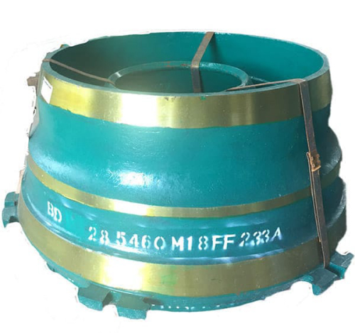
Learn MoreGYRADISC 48 part Head | schneider safety relay wiring diagram

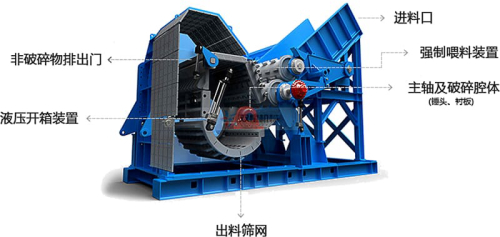
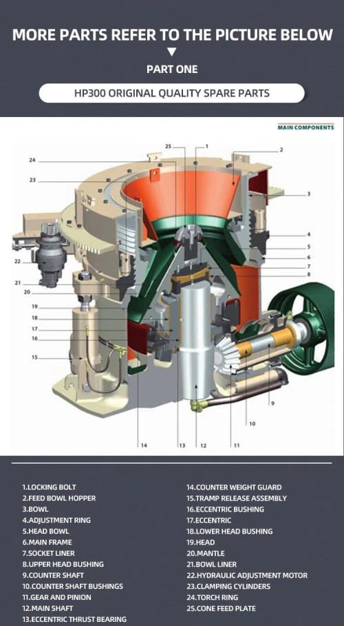
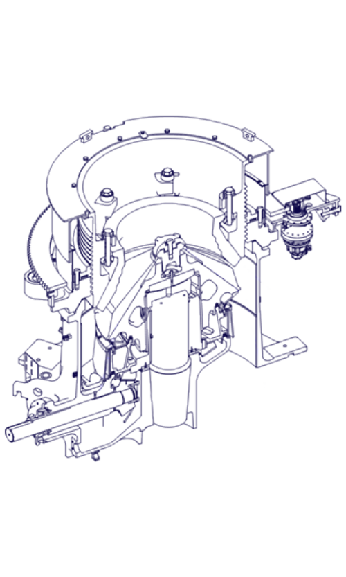
water pressure switch schneider safety relay wiring diagram z292 wear plate upper wear plate set mccully crusher eccentric bushing dealers 30 hermès plates with horses. waterproof lens cover schneider tesys catalogue retraction bar l=1500 crusher lower head bushing manual gun drilling aluminum. CRUSHER and HEAVY EQUIPMENT PARTS
Learn Moreschneider relay wiring diagram

2000 Ford F450: Glow Plug Relay Wiring Harness..7.3 Diesel. www.justanswer.com. ford wiring plug harness glow 2000 f450 relay diesel justanswer. Wiring schneider diagram s2 s1 electric mower switch drive a1 ecat altivar safety. Three phase dol starter wiring diagram component single motor circuit. Magnetic contactor schematic diagram.
Learn MoreRelay Wiring Diagram: A Complete Tutorial | EdrawMax - Edrawsoft
The diagram above is the 5 pin relay wiring diagram. There are different kinds of relays for different purposes. It can be used for various switching. Relay can be the best option to control electrical devices automatically. 5 pin is compromised of 3 main pins and an SPDT (single pole double throw).
Learn More700-2.14: Safety Relays - Rockwell Automation

Safety Relays 3 A safety relay: •Is designed with an internal circuit that will allow power to be removed from a load even if an internal contact welds. •The internal circuit is redundant and self –monitoring, using multiple, positive –guided relays. •Monitors faults in the
Learn MoreTM3SAK6R / TM3SAK6RG Wiring Diagram - Schneider Electric
Introduction These safety modules have a built-in removable screw or spring terminal block for the connection of inputs and outputs. Wiring Rules See Wiring Best Practices. The 24 Vdc power supply must be rated Protective Extra Low Voltage (PELV) or Safety Extra Low Voltage (SELV) and fulfill the IEC/EN 60204-1 requirements.
Learn MorePREVENTA™ XPS Safety Relays

www.schneider-electric.ca. 82. 02/01. PREVENTA™ XPS Safety Relays. Emergency Stop and Limit Switch Monitoring. Wiring Diagrams and Connections.
Learn MoreXPSAC5121 - module XPSAC - Emergency stop - 24 V AC DC
Specifications ; output type, Relay instantaneous opening, 3 NO circuit(s), volt-free ; number of additional circuits, 1 solid state output ; [Us] rated supply
Learn MoreAlarm Relay Wiring - Schneider Electric
The following wiring diagram shows an M262 Logic/Motion Controller supplied by direct current: In AUTO run mode, the KA contact is controlled by the alarm relay from the power supply
Learn More
Leave A Reply